This is a live document describing the current state of the ATK16 project. It is not final and will most likely never be. Follow the note archive RSS feed to be notified when significant changes to the project are introduced.
- Abstract
- Namesake
- Processor architecture
- Memory
- Interrupts
- Picture and sound
- Application binary interface (ABI)
- Toolchain
- Assembly language
- Standard library and built-ins
- Links
Abstract
ATK16 is a homegrown faux-retro 16-bit computer and ecosystem project that includes
- a non-pipelined, Von Neumann style, register-machine, central processing unit (CPU) design
- a small, custom instruction set architecture (ISA) with 4-bit opcodes, i.e. 16 possible instructions
- on-board peripherals (memory, graphics and sound processors)
- memory-mapped input and output (MMIO) for communicating with on-board peripherals as well as external peripherals such as the keyboard
- 16-bit data and address buses
- a big-endian byte order
- an assembly language
- an assembler for building software for the system
- an application binary interface (ABI), including a function calling convention and data memory representations, designed with the system’s features in mind
- a software emulator for running the built software on your development machine
- a register transfer logic (RTL) model designed in Digital capable of running the built software

The idea for the project hatched from my admiration for Ben Eater and his DIY CPU and video card projects. I was enamoured by the elegance of his systems and simply wanted to do something similar. I had none of the required knowledge for this kind of low-level CPU design work, but I had studied digital electronics for a bit in university.
The technical details are an amalgam of the features of home computers and game consoles of the 80s and 90s, without all the optimization and smart engineering. The idea of ATK16 is not to create a performant, useful system. The idea is to learn and make something that runs programs and makes bleeps and bloops.
The project started off as just the CPU design, but grew little by little to encompass also peripheral circuits as well as the development toolchain and software libraries. The scope defined in this document is approaching the final scope asymptotically. Nothing major has been added for some time and I’d like to keep it that way.
As of right now, ATK16 is capable of running text mode graphical programs with keyboard input in both the emulator and the simulator model. Sound and sprite graphics are still underway. My dream is that some day I have a big program, be it a dungeon-crawler game or some productivity software, that uses all the features available in the system in unison, and I can use that for demoing the thing.
The spec undulates in time based on what I deem possible or necessary for the system’s design. And by spec I mean a categorical product of what I have implemented thus far and what I’m planning to implement in the future. There is no written spec. In fact, this document is possibly the closest thing there is to a written spec.
Namesake
ATK, or automaattinen tietojenkäsittely, is a Finnish term that translates to “automated information processing”. The acronym is no longer used; it has been supplanted by the English acronym IT even in Finnish contexts. Being now a historical expression, the term has gained a certain affect. It’s like talking about automobiles instead of cars, or telephoning someone instead of calling them. There is also a bit of awe embedded in the expression: it takes effort to understand ATK.
Talking about ATK in current day invokes that little bit of mystique about not fully understanding how computer technology works or is supposed to work. It can also be used ironically: IT systems that malfunction, are non-optimal or just generally bad can be described as ATK in Finnish techie vernacular.
For me personally, ATK brings to mind a yellowed plastic box that’s running something like UNIX System V and some kind of corporate bookkeeping software. Entirely dull but somehow intriguing at the same time.
ATK16 is ATK with a 16-bit bus width.
Processor architecture
The processor consists of the central processing unit (CPU), the arithmetic-logic unit (ALU), the register bank and the memory unit, all connected by the data bus to each other as well as onboard peripherals such as the sound and graphics cards, as well as external peripherals like the keyboard. The processor’s purpose is to run user-written programs by executing instructions that are stored in memory.
CPU and the instruction cycle
The heart of the system is the CPU. In classical Von Neumann style, its heartbeat consists of three stages:
- Fetch: pull the next instruction from memory to the instruction register (IR)
- Decode: split the instruction into the operation code (opcode) part and argument parts
- Execute: convert the opcode into a series of control signals that operate on the arguments of the instruction, moving them between memory, registers, the arithmetic-logic unit (ALU) and the peripherals using the data bus, effectively executing the operation
The CPU is not pipelined, which means that only one instruction is being processed at once. This makes the instruction cycle and the CPU state really easy to reason about. It also induces a big performance hit: potential amortized performance is reduced to around a third.
Pipelining would allow work to be done in parallel, but also opens the door to jump hazards and other possible issues that have to be taken care of.
There is also only one core; no multicore parallelism for you.
Registers
The register bank consists of 8 general use registers
RA–RH. These are the registers that are
usually being referred to when using the word register.
There are also special registers:
- a program counter (PC) for keeping track of the program execution position
- a memory address register (MAR) for storing the memory address being accessed
- an instruction register (IR) for storing the instruction that is being executed
- a flag register (FR) for storing the ALU flags that are updated on each ALU operation
- an interrupt program counter register (IPC) for storing the program counter value when entering an interrupt service routine (ISR)
- …as well as other, unnamed registers that are irrelevant for understanding the operation of the system.
Special registers can not be accessed with the same instructions that access the general use registers.
Most instructions in the ISA have to do with moving data between these registers, the ALU and the memory. Take for example this assembly program:
ldi 0x100 RA    ; load the value 0x100 to register RA
ldr RA RB       ; read from memory address in RA (0x100) and store the value in RB
addi RB 1 RC    ; add the immediate value 1 to the value in RB and store the result in RC
🙋🏼 Note: throughout this document, I will be using assembly language examples anachronistically to demonstrate system features even though you, the reader, might not yet know how to read it. You can check out later parts of the document for a detailed description of the assembly language if you prefer learning that way, although I’ll try to write my examples in such a way that the language is comprehensible in context even without knowing the syntax or the semantics.
Using simple operations, data is being moved from the instruction arguments to a register, from the register to the MAR, from the MAR to the memory, from the memory to another register, from the register to the ALU, from the ALU to the FR and another register.
In addition, there exists the notion of memory registers, which are special memory addresses that simulate a hardware register. They exist because they can be accessed via regular memory reads and writes; no purpose-built opcodes need to be added. Most of the memory registers are MMIO registers. Accessing MMIO registers allows the user to access peripherals and do actions such as put pixels to the graphics cards or read key code values from the keyboard.
Note:
RHis conventionally reserved to be used as a stack pointer (SP), so that leaves 7 registers for general use. Note that nothing in the hardware requires a stack pointer or mandates its use. However, a stack is a nice thing to have, and reserving a hardware register for the stack pointer (instead of a memory address) makes stack operations a lot faster. Thebootstrapassembly module assumes thatRHis the stack pointer.
Arithmetic-logic unit (ALU)
ATK16 has an 8-operation ALU that takes in two values and produces a third and sets a bunch of flags. The two input values can come either from
- register X and register Y, or
- register X and an immediate value IMM between 0 and 7.
The output goes to register Z.
X, Y and Z are general use registers
RA–RH, selected by the instruction arguments.
For example, this 16-bit bitstring represents an instruction that
sums RB and RC and saves the result in
RD:
CCCC TTT LLL RRR SSS
0000 011 001 010 000
Here,
CCCCis the 4-bit opcodeALR(arithmetic-logic with register),TTTis the 3-bit target registerRD,LLLis the 3-bit left hand side registerRB,RRRis the 3-bit right hand side registerRC, andSSSis the 3-bit ALU code for the operationL + R.
The full list of ALU operations is below.
| ALU code | Operation |
|---|---|
| 0 | L + R |
| 1 | L - R |
| 2 | L and R |
| 3 | L or R |
| 4 | L xor R |
| 5 | L >> R |
| 6 | L >>> R |
| 7 | L << R |
The difference between
L >> RandL >>> Ris that the first one is a logical right shift, meaning that the new bits at the most significant end of the word are always set to zero. The second one is an arithmetic right shift, meaning that the new bits all match the most significant bit of the original word. This is useful in signed arithmetic, where a right shift should result in a negative result (most significant bit = 1) when applied on a negative number.
Keep in mind that the operands are always 16-bit. Any result that cannot be represented with 16 bits will over or underflow to fit. In such cases, a flag is set to signal that the arithmetic result is not correct in a real world sense.
After each ALU operation, the flag register (FR) is updated with the new flags. The flags are as follows:
| Flag | Interpretation |
|---|---|
| Carry (C) | In unsigned arithmetic, the result is not correct |
| Overflow (O) | In signed arithmetic, the result is not correct |
| Zero (Z) | The result is zero |
| Sign (S) | In signed arithmetic, the result is negative |
The ALU assumes two’s complement negative numbers, which makes it possible to use the same operations for both unsigned and signed arithmetic. As a user you have to choose which one you’re using, and interpret the ALU flags and the result value correspondingly.
Memory
The CPU is connected to the onboard memory unit. The memory unit
consists of multiple components that are accessed through a single
address bus. The address bus width, i.e. the size of the address, is
16 bits. This means that the largest address that can be represented
is 2^16 - 1 = 0xFFFF. In other words, there are 64K
addresses.
The memory consists of a couple of major segments: the ROM, the RAM and the MMIO segment.
| Segment | From | To |
|---|---|---|
| Read-only memory (ROM) | 0x0000 | 0x7FFF |
| Random access memory (RAM) | 0x8000 | 0xE7EF |
| – Stack | 0x8000 | X |
| – Heap | X | 0xE7EF |
| MMIO segment | 0xE7F0 | 0xFFFF |
| – MMIO registers | 0xE7F0 | 0xE7FF |
| – Sprite memory (PPU) | 0xE800 | 0xFFFF |
| – Text memory (TPU) | 0xF800 | 0xFFFF |
Let’s look at each of these in detail.
The X between the stack and the heap represents some dynamic point that they both grow toward. If the stack and heap overlap, weird things and data loss may occur.
ROM
The ROM is a memory that contains constant data and program instructions. The ROM can not be written to during runtime, only during development using tools external to the ATK16 system.
The ROM is initialized with a ROM image that is produced by the ATK16 assembler. The assembler takes in your assembly and produces a binary image exactly 64 KB in size.
✍🏻 Vocabulary check: an image is just a binary file full of bytes that make sense to a specific system or program. Usually images contain executable instructions, but there are also disk images that contain the contents of a hard drive, byte for byte. Here we are talking about the first type of image.
With a physical ROM (e.g. EEPROM), the ROM image would written to the ROM using a separate programmer circuit. We have an easier time with the ATK16 emulator, which simply takes in the filesystem path to the image as a command line argument and reads it directly from the file. The Digital simulator model similarly supports loading the image into the ROM component.
On boot, the program counter (PC) is set to zero. When the machine starts up, the first instruction cycle reads from the address 0, which is the first word of the ROM image. This segment of the image is something akin to the boot sector of modern computers: its task is to set up critical things, such as the stack pointer, and then jump to the actual program segment.
Between the boot sector and the program segment, which contains the user-supplied program code, there is the vector table and the data segment. The vector table is a sequence of important, spec-defined values located at predefined addresses.
For example, at address
0x14you should find the value0x8000. This is the address of the lowest stack address, and the beginning of the stack segment.
The vector table needs to exist in a low address segment, since
the operation ldi (load immediate), which is the only
way to load values from instruction arguments to registers, can only
load 2^9 = 512 distinct immediate values, starting from
zero. Loading larger values with ldi requires you to
first store the value in a convenient low address
(i.e. 0x1FF or less), and then load that with
ldr (load from address in register).
Large spec-defined values exist in the vector table and user
defined values exist in the data segment. The data segment
is dynamically sized and grows with each word of data stored in it.
You can use the @data assembler directive to install a
new word of data into the data segment.
RAM
The RAM is a read-and-write memory that contains both the stack
and the heap. The stack is a “hardware level” thing: there are
instruction mnemonics (spu and spo) for
manipulating the stack. The stack grows upwards toward larger
addresses.
🙋🏼 Side note: the mnemonics
spuandspoare actually macros and not primitive instructions on the ATK16. Macros are a way of constructing compound mnemonics that are expanded to their primitive constituent parts during assembly.
The RAM is full of scrambled, uninitialized gibberish at startup.
The first instructions in the boot sector are responsible for
setting up the stack pointer in register RH and
pointing it to the beginning of the RAM and the stack segment,
i.e. 0x8000.
The heap is a “software level” thing. There is nothing in the assembler that indicates the existence of a heap, or a heap allocator for that matter. The heap is purely defined in software. You can have a running ATK16 without a heap and instead just have static allocations and a big chunky stack. There is a standard library module for setting up a heap allocator though; you don’t have to invent one yourself. The heap grows downwards toward smaller addresses.
Note that you can technically forgo the stack as well, but that’s kind of wild.
MMIO segment
The memory-mapped input and output (MMIO) segment is a part of the address space that is concerned with accessing and manipulating peripherals and special registers. Some of the addresses in this segment are read-only, some are write-only, and some may be read-write. Running a non-supported read or write operation results in gibberish data or unexpected behaviour.
In the beginning of the MMIO segment there is a small sliver of address space that houses the MMIO registers.
| Address | Name | Description |
|---|---|---|
| 0xE7F0 | terminal_addr |
Write-only, write characters to the terminal peripheral |
| 0xE7F1 | keyboard_addr |
Read-only, read key codes from the keyboard peripheral |
| 0xE7F2 | gr_mode_addr |
Write-only, set the graphics mode (0 = disabled, 1 = text mode, 2 = sprite mode) |
| 0xE7F3 | iset_addr |
Write-only, set the critical section flag (see Interrupts) |
The MMIO segment continues with the sprite and text memories. These are separate memories and not a part of the main RAM. Note that the sprite and text memory address spaces overlap: this is fine, because the two are never used at the same time. Sprite memory is an auxiliary memory in the picture processing unit (PPU) and text memory is an auxiliary memory in the text processing unit (TPU). The graphics mode determines which is producing a video signal to the VGA peripheral. See the Picture and sound section for more detail.
Interrupts
The ATK16 is a single-tasking machine, but there is still one mode of concurrency: interrupts. Interrupts are a mechanism for pausing the current execution and running a bit of special program code called an interrupt service routine (ISR) instead, when a time-sensitive event occurs. When the ISR finishes, the CPU restores the paused program and continues where it left off, as if nothing happened in the meantime.
To store and restore the program state, the interrupt handler uses special instructions to move the program counter (PC) value into and out of the interrupt program counter (IPC) register.
So what causes interrupts? The most common cause would be a
keyboard key press. On key press, the keyboard module sets an
interrupt line from 0 to 1. This is referred to as an
interrupt request (IRQ). There are four interrupt lines
available for different peripherals to use. These are not
configurable: a keyboard always uses IRQ0. The rest are
reserved for future designs.
At the beginning of each instruction cycle, a component of the CPU called the interrupt handler checks if any of the IRQs are set, and prioritizes the one with the lowest index. If there is no IRQ active, the CPU continues normally. If there is an active IRQ, the handler overrides the IR and runs a special instruction to save the PC to IPC as well as read the new PC value from the vector table. Each interrupt line has an entry in the vector table that tells the system where in memory to find the corresponding ISR code. The PC is updated with this address and execution continues from the beginning of the ISR.
The ISR code has some obligations. It is the ISR’s responsibility to leave the register bank seemingly untouched when control is returned back to the main program. To do this, all register values that the ISR erases by using the register for its own logic must be saved on the stack, and restored before returning. This is similar to the function calling convention, where functions are obligated to clean up after themselves.
Interrupts are a source of concurrency since IRQs might be serviced at any point in the program, possibly leading to data inconsistency issues.
Consider this scenario: a main program does three things in a loop:
- it reads a value (
n) from memory into a register, - it increments it by one (
n + 1), and - it stores it back in the same memory address.
An interrupt pauses the execution right after the memory load
(between steps 1 and 2). The ISR decrements the same value in memory
(n - 1) and returns to the main program. The main
program is now in an unexpected state: the loaded value in the
register is one more than the one in memory
(n > n - 1). Continuing forward, the program
increments the register value by one (n + 1) and stores
the result in memory. The value in memory effectively jumps from
n - 1 to n + 1. So much for incrementing
by one. It’s as if the ISR never decremented the value in the first
place.
This is called a race condition: the effect of a program depends on the timing of concurrent tasks. To avoid race conditions, a section of code can be declared a critical section. A critical section can not be interrupted. If an interrupt request happens to come in during the execution of a critical section, it stays active but control won’t be transferred to the ISR. When the critical section ends, pending interrupt requests are immediately processed.
All parts of your program that access the same data as your ISRs should always be declared critical sections!
Note: upon entering an ISR, the system itself toggles the critical section flag. This is done to make sure that only one interrupt can be running at once. Concurrent interrupt requests are serviced sequentially in index priority order.
Interrupts caused by events in physical peripherals are called hardware interrupts. Some computers also support software interrupts, i.e. interrupts triggered from program code. ATK16 does not have these per se, but it does support setting the critical section flag from software via an MMIO register. This is used to declare a critical section in program code.
Picture and sound
Video and audio are the primary means of providing feedback to the user about what is happening in the machine. The video part is handled by the two onboard graphics processors: the TPU and the PPU.
On startup, the graphics mode memory register is set to disabled (0). To activate the TPU, set the value to text mode (1), and to activate the PPU, set the value to sprite mode (2).
Text processing unit (TPU)
The TPU is a graphics processor that produces a 40 x 30 character VGA output signal.
 The TPU has 3 major components:
- The character memory (ROM)
- The text memory (RAM)
- The VGA signal generator
The character memory is a bit of ROM memory that is loaded with a
character memory image. This is a small binary image that
contains pixel data that allow the VGA signal generator to draw a
character based on its character code. The image can be generated
with the charmem.py tool. The character set used in the
TPU contains 256 8x8 glyphs.
The text memory is a block of RAM that contains character codes.
One character of text can be represented in one 8-bit byte of space.
For ease of implementation, each 40 character row is represented by
2^6 = 64 words.
This is obviously wasteful, since we’re losing 24 words to undisplayable data every row. We could even pack two characters into one word, in total reducing the size of the text memory to less than 50%!
These are improvements that might be implemented later, but for now, I’m focusing on getting the thing working.
You can write into the text memory using regular memory
instructions with the MMIO addresses from 0xF800
upwards.
The VGA signal generator is a circuit that tirelessly iterates over the character and text memories, synthesizing their contents to generate pixel data for each pixel of the 320x240 VGA display.
Picture processing unit (PPU)
The name and the design for the PPU are shamelessly stolen from the Nintendo Entertainment System (NES).
TBD.
Audio processing unit (APU)
TBD.
Application binary interface (ABI)
The ABI is a platform specified set of details that describe the interface between two executable binary program modules. These could be for example a compiled application and a compiled library in a modern computer. The details of the ABI include things like how to call functions and how to represent data in memory.
In ATK16, there are never two separate binary objects that need to interface each other, since all source modules supplied to the assembler are compiled into a single output image. There are no build units, no linking stage, and no libraries to load. Everything is assembled into a single image. Without two things interfacing, the term application binary interface is admittedly a bit weird, but I still use it because it is commonly used to talk about the details that I want to talk about in this section.
Build units and a linking stage are mostly a historical byproduct of development systems that could not hold the entire build context in memory at the same time. Building nontrivial projects was made possible by allowing the compiler to work on only a little bit at a time. This is useful even today when building very large projects.
When compiling for the ATK16, this issue is nonexistent. Any modern system has enough RAM to build a max size, 64KB ROM image.
Instruction set
The instruction set is minimum instruction set computer
(MISC) inspired. It is not truly minimal; multiple instructions, for
example jpr ja brr could probably be
replaced by elaborate multi-jump schemes. However, it is still quite
small, and the opcodes fit nicely in 4 bits (16 available
values).
| Opcode | Mnemonic | Description | Arguments |
|---|---|---|---|
| 0000 | alr | Arithmetic-logic with register | left reg, right reg, target reg |
| 0001 | ali | Arithmetic-logic with immediate | left reg, imm value, target reg |
| 0010 | ldr | Load from address in register | address reg, target reg |
| 0011 | str | Store to address in register | value reg, address reg |
| 0100 | ldi | Load immediate | immediate value |
| 0101 | jpr | Jump to address in register | address reg |
| 0110 | jpi | Jump to immediate address | imm address |
| 0111 | brr | Branch to address in register | imm flag selector, address reg |
| 1000 | bri | Branch to immediate address | imm flag selector, imm address |
| 1001 | lpc | Load program counter | target reg |
| 1010 | – | – | – |
| 1011 | – | – | – |
| 1100 | isrp0 ¹ | ISR process 0 | – |
| 1101 | isrp1 ¹ | ISR process 1 | – |
| 1110 | rti | Return from interrupt | – |
| 1111 | hlt | Halt | – |
¹
isrp0andisrp1are not intended to be used in program code. They are “magic” instructions that override the current instruction when servicing an interrupt request. See Interrupts.
All instructions have a fixed 16-bit width. 4 bits are reserved for the opcode and 12 bits are reserved for the argument data.
Register arguments use a 3-bit selector value to pick one of the
8 general use registers RA–RH. Immediate
arguments are either 3 bits wide (ali) or 9 bits wide
(ldi, jpi, bri).
Citing the ROM section:
The vector table needs to exist in a low address segment, since the operation
ldi(load immediate), which is the only way to load values from instruction arguments to registers, can only load immediate values up to2^9 - 1 = 511. Loading larger values withldirequires you to first store the value in a convenient low address, and then load that withldr(load from address in register).
This limitation gives rise to a common pattern where larger
values are stored in low addresses in the data segment, and then
loaded to registers with a combination of ldi and
ldr.
Unconditional jumps (jpi, jpr) do what
it says own the label: they jump to the given address without
checking any condition. Conditional jumps, or branches
(bri, brr) use a 2-bit flag selector to
check if a specific flag register (FR) flag is set (see ALU), and only then do the jump. If the specified
flag is not set, the branch instruction is a no-op.
In general, ATK16 uses absolute addressing everywhere, except in
the immediate jumps (jpi, bri), which use
relative addressing (result = PC + address). This is
useful because most of the immediate jumps are short distance and
can be represented in 9 bits if using relative addressing, but not
absolute addressing. Long jumps must use a ldi +
ldr + jpr pattern, which is based on the
ldi + ldr pattern that is used to read
large values to registers.
For more detail on how arguments are packed into the instruction
word, see source code of the ucode.py command line
tool.
Calling convention
To call a function, the caller must set the first argument to
RA, the second to RB, etc. Naturally, a
maximum of seven (7) arguments can be passed, since RH
is the stack pointer by spec. The caller then pushes the return
address PC + 1 to the stack and jumps to the function
address.
If you need to pass more than 7 arguments, consider passing a pointer to a struct instead.
The callee must make sure that the registers contain the same
values at return time as they did at call time, with the exception
of the return value register, which is defined as RG by
spec. To do this, the called function must save and restore any
registers it uses in its body.
The idea here is that register values are locally consistent. All register manipulations should be explicit in program code. If a function call would be allowed to clobber registers (other than
RGwhich is allowed to be clobbered), it would be difficult to reason about the local behaviour of a program.
The mechanical parts of this calling convention are implemented
by the calli/callr and return
built-in macros. The calling user only needs to set up arguments in
the correct registers and read the return value from the return
value register.
Note that function calls are similar to interrupts in multiple ways:
| Function call | Interrupt |
|---|---|
The return address PC + 1
is saved on the stack |
The PC is loaded to the IPC register |
| The PC is replaced by the function address | The PC is replaced by the ISR address |
| The called function is responsible for restoring register state | The ISR is responsible for restoring register state |
| The function returns by jumping to the return address | The ISR returns with the instruction
rti |
Data type representation
This is an area of active development.
ATK16 has a canonical memory representation for primitive data types like integers and booleans, as well as some compound data types like strings and structs. The standard library expects data to be stored using these representations. Users are free to define custom memory representations for new types and implement procedures to access and manipulate them in their applications.
All data types defined here align with the 16-bit word boundary.
| Type | Bits | Representation |
|---|---|---|
| Unsigned integer | 16 |
Binary number |
| Signed integer | 16 |
Two’s complement, binary number |
| Character | 16 |
8 bits padding, 8 bits of character code |
| Boolean | 16 |
Zero for false, any other
bitstring for true |
| Fixed-point fraction with base b | 16 |
Binary integer (base only known in compile time) |
| Array of n elements of type a | n x sizeof(a) |
Consecutive bytes / words in memory |
| String of n characters | 16 + n x 16 |
Pascal string, i.e. the length followed by the data |
| Struct with fields a0, a1, … | sum(sizeof(aN)) |
Consecutive field representations in memory |
🙋🏼 Future note: A new packed string representation might happen in the future. In a packed string, two 8-bit characters are stored in one 16-bit word. This would mean that the 16-bit word alignment rule is relaxed to 8-bit byte alignment string-internally. The string representation as a whole is still padded to the word boundary.
Toolchain
The ATK16 project is a combination of designs and implementations. In addition to the Digital simulator model and the emulator, which are implementations of the system itself, there are also a number of command line tools. The table below summarizes the major directories available in the ATK16 monorepo.
| Name | Description |
|---|---|
| atk16_emu | Software emulator |
| atk16_asm | Assembler |
| digital_diagrams | Digital logic simulator model |
| atk16_syntax | VSCode syntax highlighting for ATK16 assembly |
| atk16_utils | CLI tools to generate the character memory image etc. |
| atk16_projects | Example application projects |
| test | Automated tests
(make test) |
| * atk16_bytecode_compiler | Python -> ATK16 assembly compiler |
| * atk16_ast_walking_compiler | Python -> ATK16 assembly compiler |
* ) These are more of an academic experiment in compilers and not a serious component of the ATK16 toolchain. The compilers are not implemented to a working degree and only support a very limited subset of Python 3. It turns out that while trying to compile a language that is totally not meant to be used as a systems language is a fun thing attempt, alas, it does not lead to a fruitful outcome.
All programmed tools are written in reduced dependency Python 3.
The only external dependencies are getch and
pygame, which are used for unbuffered keyboard input,
and audio and video, respectively.
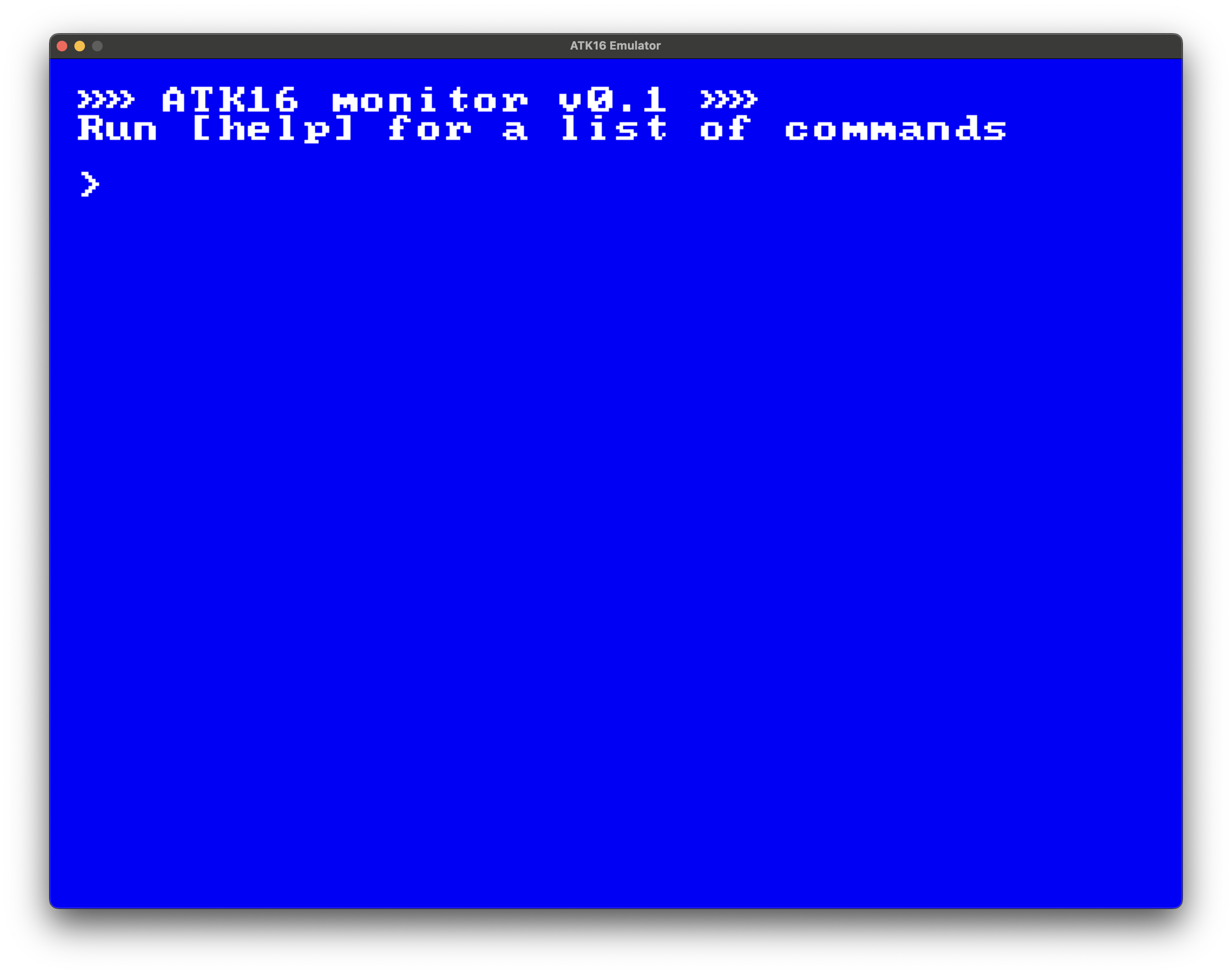
The easiest way to get something running is to use the emulator.
Follow the steps below to get the monitor application
booted up.
git clonethe ATK16 repository- Set up a suitably modern Python 3 environment and install the ATK16 toolchain as a local Python package:
$ pip install .- Assemble the
monitor.atk16source into a ROM image:
$ atk16c resources/asm/monitor.atk16 -o out/monitor.binThe assembler also produces another file in the output directory called
out/monitor.bin.dbgthat contains debug symbols. The step debugger uses these to map instruction words to their original source lines.
- Load the built image into the emulator and boot it up:
$ atk16emu out/monitor.binYou can supply the -d flag to the emulator to start
the program in step debugger mode. Press ? to see usage
instructions.
$ atk16emu -d out/monitor.binAutomated tests
If you plan to make changes to ATK16 components you can run the test suite by running the following in the monorepo root:
$ make testThese tests utilize some useful utilities that can be useful when
writing tests for your own application code as well. See the test
source code in the test directory for details.
Assembly language
Assembly languages are a family of low-level programming languages whose statements strongly correspond with the machine code instructions of their target platform. ATK16 assembly is an assembly language designed to be understood by the ATK16 assembler and compiled into a ROM image for ATK16 to read and execute.
The language aims to be as human-readable as an assembly language realistically can. To aid in this, the assembler supports macros, which allow the programmer to construct named reusable blocks of code that are expanded to primitive instructions at assembly time. Using macros has no effect on performance when compared to writing out instructions by hand.
Here’s a code snippet:
@use monitor_macros:*

@include %bootstrap
@include %std_mem
@include %std_term
@include %std_bump_alloc

;; Constants
@data text_buffer_size  2048
@data input_buffer_size 64

;; Global variable pointers
;; 0xE800 - 0xEFFF: sprite buffer space that is unused in this program
@data text_cursor_p  0xE800
@data input_buffer_p 0xE801
@data input_cursor_p 0xE802

@data title_string    " »» ATK16 monitor v0.1 »»"
@data subtitle_string " Run [help] for a list of commands"
@data prompt_string   " > "

@label main
;; initialize heap allocator
  calli bump_reset

;; initialize global variables
;; text_cursor_p = text_mem
  ldi text_cursor_p RA
  ldr RA RA
  ldi vt_text_mem RB
  ldr RB RB
  str RB RA
Let’s dissect this.
🙋🏼 The pandoc-based code highlighting that you’re seeing on this page naturally does not support ATK16 assembly. I try to use highlighting for other programming languages to get some sort of readability.
Statements
Statements are sequences of code delimited by a newline. Other
types of whitespace (i.e. not newlines) separate terms in a
statement. Statements that start with @ are called
directives. Comments start with a semicolon ; and end
at a newline character or EOF.
Indented statements are instructions or constant values. The indentation is only a convention that makes it easier to visually separate directives from the rest of the program. Non-indented instruction or constant value statements are permitted but are considered unconventional.
An instruction starts with a mnemonic (e.g. ldi)
that is either a primitive instruction (see Instruction set) or a macro. Macros are
either user-defined or built in to the assembler (such as
calli). Constant value statements are just numeric
values.
These are all valid statements:
  0xFF
  0b1
  10
  ${ord("A")}      ; evaluate Python expr to value 65
  jpi main         ; jump to label "main"
  bri zero branch  ; jump to label "branch" if zero flag is set
A numeric constant must be representable in 16 bits.
Symbols RA–RH, carry,
overflow, zero and sign are
defined for convenience and evaluate to numeric values
0–7, 0, 1,
2 and 3 respectively.
You can use ${ ... } to evaluate an arbitrary Python
expression as part of a statement.
@include and
@use
At the top we see some assembler directives:
@include and @use. These directives are
similar in spirit: they include other code into the assembly
context. @include file injects the contents of the file
file.atk16 at the location of the directive. File names
prepended with a % sign are Builtin modules.
For you C and C++ programmers, there is an implicit
#pragma once in every module: including a file is
idempotent. Even if you @include a file multiple times,
only a single copy of the contents will be assembled into the output
image.
You can use @use file:* to import macros from a
Python module called file.py. Macro modules are Python
files that define a dictionary called extensions that
maps symbol names to functions that returns a list of lists of
statement terms. Here’s a snippet from the
monitor_macros.py file that the above assembly code
uses:
from atk16_asm.asm_ops import *

expansions: dict[str, Callable[..., ExpandResult]] = {}
def register_macro(func):
    expansions[func.__name__] = func
    return func

@register_macro
def m_newline(r1: str, r2: str) -> ExpandResult:
return [
    *expand_ldi("text_cursor_p", r1),
    *expand_ldr(r1, r1),
    *expand_ldr(r1, r2),
    *expand_slri(r2, "6", r2), # cursor = cursor / 64
    *expand_addi(r2, "1", r2), # cursor = cursor + 1
    *expand_slli(r2, "6", r2), # cursor = cursor * 64
    *expand_str(r2, r1),
]
There is only one namespace and no scoping in ATK16 assembly. If
you @include or @use a resource in one
file, its contents may become visible to other files as well,
depending on the inclusion tree traversal order. Library developers
are instructed to prefix all symbols with the library name so that
the probability of a namespace clash is reduced. Although, since all
assembly is done from source code only, you can fix namespace
conflicts with a simple search-and-replace.
However, Python macros
@use’d in an@include’d assembly module are never visible in the parent includer context. This is because@includecreates a separate assembler context that does not leak its bindings to the parent context.
@data and @let
Next, you can see some @data directives. These are
used to inject constant value bindings to the data segment,
which is a location in memory whose starting address is determined
with the @data_segment directive. The
bootstrap module, which is the recommended system
entrypoint for most programs, defines a data segment that can be
used in user programs.
A constant binding @data X <value> injected
into the data segment is available in the rest of the program as if
it was defined with a label directive: @label X. The
data is represented in memory according to the Data type representation spec.
Currently, only integer and string values are supported.
@let X Y can be used to define symbol bindings that
only exist during assembly time. This is useful for giving name to
otherwise magic numbers. Referencing the symbol X
simply does an environment lookup and evaluates to
Y.
@label and
@address
The @label main statement defines a label called
main that points to the address in ROM that contains
the instruction or datum on the following line. Labels are a way to
refer to a specific memory location without knowing its absolute
address. Labels can be used in most places where a numeric value is
expected. The most common use case is as the target of a jump
instruction:
@label loop
    jpi loop
This snippet would enter an infinite loop by jumping to itself on every cycle.
The @address <number> statement isn’t used in
the above snippet. It allows the programmer to insert instructions
or data in a specific absolute location, which is required when
defining the vector table in the bootstrap module, for
example.
The assembler will notice if multiple program segments try to
write to the same location in memory. Only one word can exist at a
given address, so the assembler will abort as it does not know how
to proceed. There exists a directive pair called
@begin_override and @end_override that
disable this behaviour and instead use the most recent definition,
discarding the older one. This is useful e.g. for defining custom
ISRs in the vector table, overriding the default no-op routines.
Syntax highlighting
The ATK16 monorepo contains the source code for an ATK16 assembly
language syntax highlighting VS Code extension in the
atk16_syntax directory. Follow the README in the
directory for installation instructions.
Standard library and built-ins
The ATK16 assembler ships with a number of built-in assembly program modules that you can include in your program. You can use the following syntax to include a built-in module.
@include %std_memHere, std_mem is the name of the module. The
percentage sign tells the assembler to look for the module in the
built-ins directory.
bootstrap
The bootstrap module is a recommended entrypoint for
user programs written for the ATK16. It handles all the necessary
ceremony to set up the stack, the vector table and other boilerplate
things that you as the programmer would otherwise have to do
manually. To use it, simply use @include %bootstrap as
the first statement in your main program module, and then define a
label called main that the bootstrap module will jump
to when it’s done.
TBD.
